描述
Battery Power Monitor Multifunctional Voltage Current Coulometer APP Control 0‑120V 0‑400A
Item Type: Battery Monitor
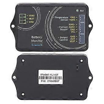
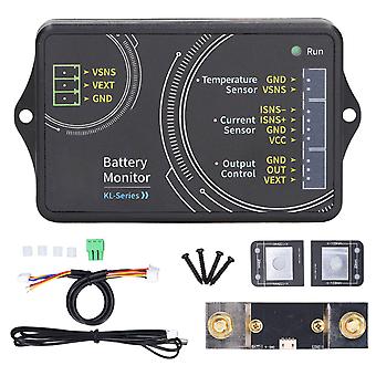
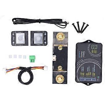
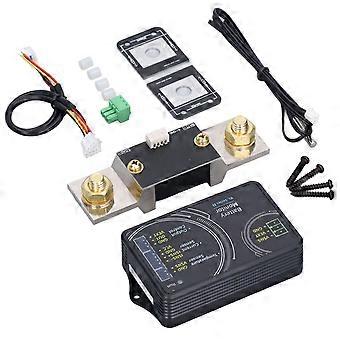
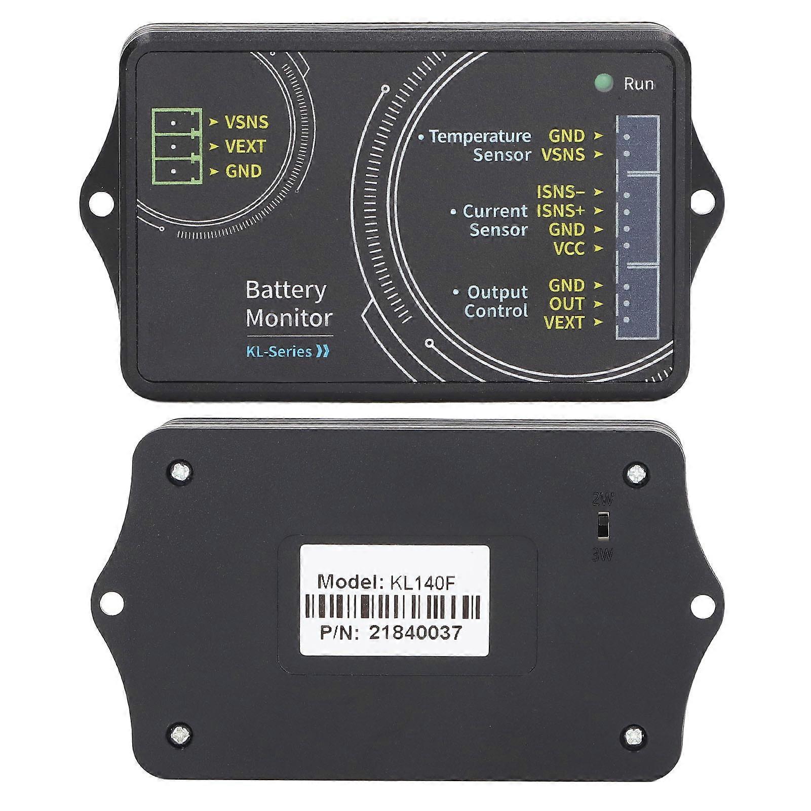
Model: KL140F
Material: ABS
Application: Electric power value detection
Control Method: Mobile APP
Sampling Method: Sampler
Voltage Measurement Range (External Power Supply): 0~120V
Voltage Measurement Range (Self Power Supply): 10V~120V
Voltage Resolution: 0.01V
Current Measurement Range: 0~400A
Current Resolution: 0.1A
Relay: No relay is provided, you need to configure it yourself
Temperature Measurement Range: -20℃~120℃
Capacity Display Range: 0%~100%
Power Measurement Range: 0~72KW
Power Resolution: 0.01W
AH Measurement Range: 0~9999.99AH
Capacity Resolution: 0.001AH
WH Measurement Range: 0~9999.99kWH
WH Resolution: 0.01WH
Bluetooth Communication Distance: Maximum Approx. 10 meter / 32.8ft (barrier free)
Voltage Accuracy: ±2%+3 words
Current Accuracy: ±5%+10 words
Sampling Rate: 1 time/second
Measurement Board Power Consumption: About 0.4W
Over Power Protection: 0~99999.99W
Negative Overcurrent Protection: 0~50A/100A/400A/600A
Forward Overcurrent Protection: 0~50A/100A/400A/600A
Overvoltage Protection: 0~120V/600V
Under Voltage Protection: 0~120V/600V
External Over Temperature Protection: 0℃~120℃
Mobile Terminal Control:
1. For Android mobile APP Instruction
(1) Download the APP
(2) Mobile App software installation. This software only supports for Android 5.0 and above systems. During the installation process, you will apply for positioning services. Please agree and open the positioning services. This manual corresponds to software version 1.0, and different versions may be slightly different. It is recommended to upgrade to the latest software for a better user experience.
1. For iPhone mobile APP Instruction
(1) Download the APP and search for KL series in the software store to download.
(1) Mobile APP software installation, the software only supports for iOS 9.0 and above systems, the software will be accessed when the software is connected to Bluetooth for the first time, please agree to access Bluetooth. This manual corresponds to software version 1.0, and different versions may be slightly different. It is recommended to upgrade to the latest software for a better user experience.
(3) Software update, you can get the latest software from the software store. The for iOS software version corresponding to the current manual is 1.0.
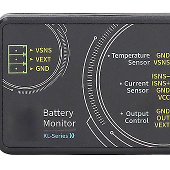
Wiring :
1. Self Powered Wiring Mode: If the voltage range of the battery under test is between 10-120V, the self powered wiring method can be used. First, turn the power supply selection interface switch to 2W, and then connect the positive pole of the battery to the battery. At the power supply interface Vsns, this line does not need to be particularly thick, 1-2.5 squarelines can be used, be careful not to connect the positive pole of the battery incorrectly. The negative electrode of the battery is connected to the screw marked with the battery GND mark on the sampler. The negative electrode of the charger and the negative electrode of the load are connected to another screw of the sampler. It is better e a copper nose to connect firmly; The current color is green, the remaining capacity value increases, and the current color is sky blue during discharge, and the remaining capacity value decreases.
2. External Power Supply Wiring Method: The voltage range of external power supply measurement is 0-120V. First, turn the power supply selection interface switch to 3W, connect the positive pole of the external power supply to the power supply interface VEXT, and connect the negative pole of the external power supply to GND; Then connect the positive pole of the battery to the measurement interface Vsns in the power supply interface when wiring; note that the positive and negative poles of the external power supply should not be connected incorrectly or reversely. The negative electrode of the battery is connected to the screw marked with the battery GND mark on the sampler. The negative electrode of the charger and the negative electrode of the load are connected to another screw of the sampler. It is better e a copper nose to connect firmly; The current color is green, the remaining capacity value increases, and the current color is sky blue during discharge, and the remaining capacity value decreases.
3. Connection Method of External Power Supply to Relay: The working power of the relay is provided by the external power supply. If the relay is connected, an external power supply with the same working voltage as the relay should be provided. Connect the control ports of the relay to the OUT and VEXT of the Output Control of the measurement module respectively; connect the positive pole of the external power supply to the VEXT of the Output Control, and the negative pole of the external power supply to GND; be careful not to connect the positive and negative poles of
-
Fruugo ID:
403121039-855960103
-
EAN:
9361326327143